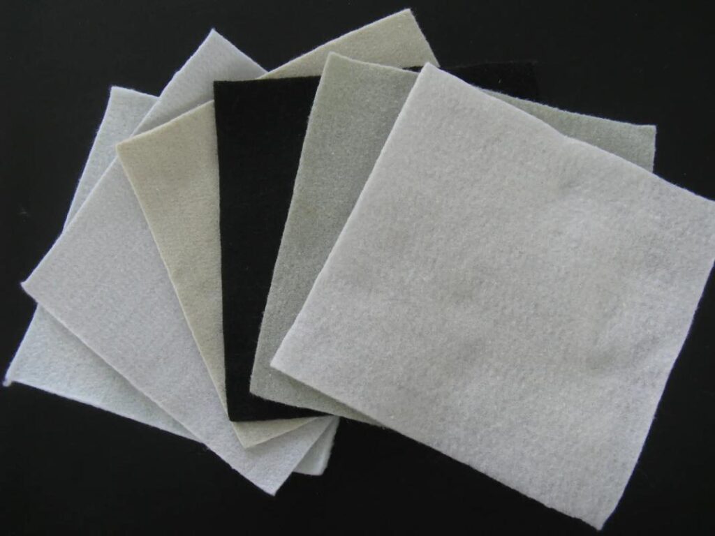
1. What Is Geogrid Reinforcement?
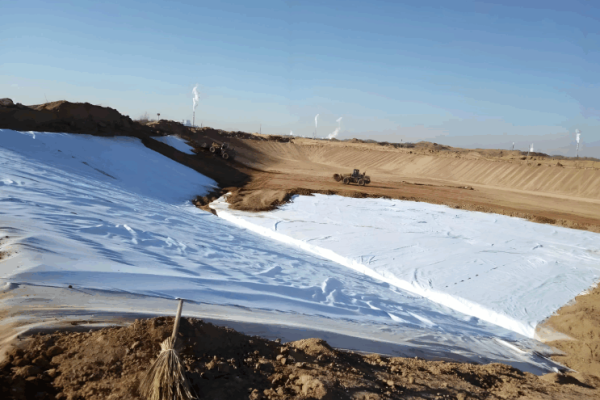
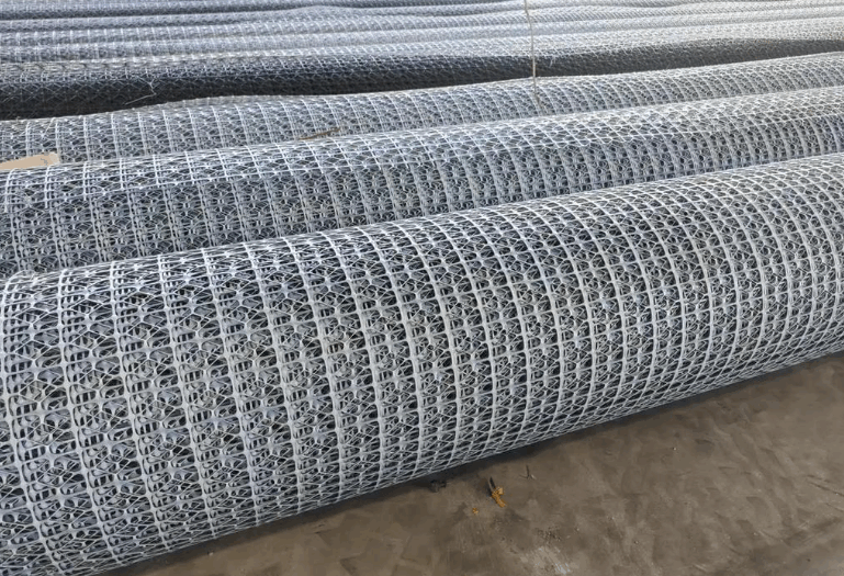
Geogrid reinforcement is a mainstream soil stabilization technology in geotechnical engineering. It adopts mesh geosynthetic materials made of high-molecular polymers (HDPE, PP, PET) or steel composites laid inside soil mass. Through interlocking and friction between geogrids and soil particles, the mechanical properties of soil are improved to boost the overall stability of foundations, slopes and retaining structures. As core flexible reinforcement materials, geogrids effectively compensate for natural soil’s defects of low tensile and shear strength, solving common engineering problems such as soft foundation settlement, pavement cracking, slope sliding and retaining wall deformation. They are widely applied in municipal roads, transportation infrastructure, water conservancy slope protection, site filling and other civil engineering projects.
Compared with traditional soil reinforcement methods, the greatest engineering value of geogrid reinforcement lies in breaking the inherent limitation that natural soil can bear compression but barely tension. The coordinated stress-bearing mechanism between materials and soil disperses concentrated loads and restricts lateral soil displacement. It cuts project costs, shortens construction periods and greatly improves the long-term service stability of civil structures, making it a highly cost-effective standardized technical solution for modern geotechnical reinforcement projects.
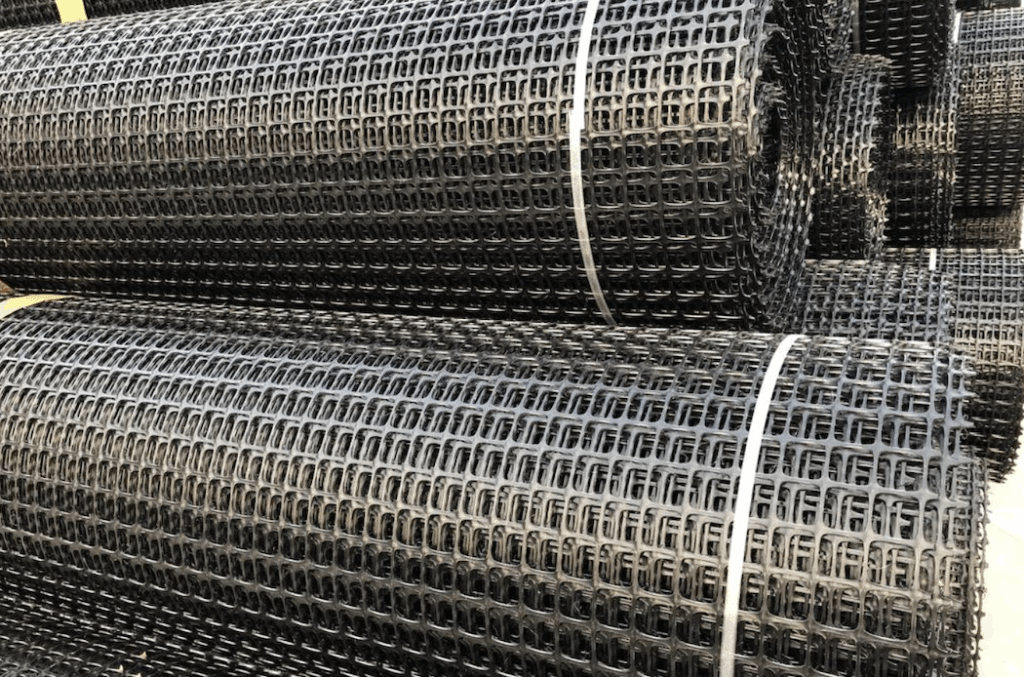
2. Working Principles of Geogrid Reinforcement
The stabilizing effect of geogrid reinforcement does not rely on simple material laying. Instead, a stable composite “soil-geogrid” structure is formed via coordinated physical and mechanical interactions, consisting of four core mechanisms supporting long-term soil reinforcement.
First, interlocking and friction constraint of soil. Regular mesh openings of geogrids fully wrap and interlock backfill soil particles. Soil embedded in mesh holes forms an integrated interlocking structure that sharply raises friction at the soil-geogrid contact surface. It effectively limits lateral sliding and vertical deformation of soil under loads, fundamentally reducing soil loosening and settlement. This mechanism serves as the core stress basis for soft foundation reinforcement and subgrade leveling.
Second, tensile load bearing and load distribution. Natural soil has almost no tensile capacity, while geogrids deliver excellent uniaxial or biaxial tensile strength. When soil deforms under vehicle loads, self-weight or external pressure, geogrids rapidly bear tensile stress and evenly spread local concentrated loads to a wider soil area. This avoids structural damage caused by local overload and reduces differential settlement of subgrades and fill structures.
Third, improved soil shear strength. Combined with interlocking constraint and tensile force transfer, composite soil achieves drastically enhanced shear bearing capacity to resist shear failure. It greatly lifts foundation bearing capacity and anti-sliding stability of slopes, meeting stress requirements of complex working conditions including high fills, heavy-load roads and water-facing slopes.
Fourth, long-term stable protection mechanism. Premium geogrids feature corrosion resistance, anti-aging performance and low-temperature deformation resistance. Buried in soil, they maintain stable mechanical properties long-term, preventing structural damage induced by rain infiltration, temperature fluctuation and soil consolidation, and significantly extending the overall service life of civil engineering works.
3. Main Types and Differences of Geogrids for Reinforcement
Two major types of geogrids are commonly used for soil reinforcement in engineering: uniaxial geogrids and biaxial geogrids. They differ greatly in mechanical performance, stress characteristics and applicable scenarios, serving as core criteria for engineering material selection. Accurate distinction of their applicable cases can prevent reinforcement failure resulting from improper selection.
3.1 Uniaxial Geogrids
Uniaxial geogrids only deliver high tensile strength along the longitudinal direction with weak transverse tensile performance, bearing concentrated unidirectional forces. Manufactured via uniaxial stretching of high-molecular polymers, their molecular structures are highly aligned along the force-bearing direction, offering high tensile strength and low elongation to sustain continuous large unidirectional tension.
This type fits projects requiring unidirectional force bearing and strong anti-sliding capacity, mainly used for mechanically stabilized earth retaining walls, high-fill slopes, embankment slope reinforcement and steep slope protection to counteract unidirectional sliding thrust of soil.
3.2 Biaxial Geogrids
Biaxial geogrids are produced through biaxial stretching, featuring uniform and stable tensile strength in both longitudinal and transverse directions with no directional restrictions on stress bearing. They disperse plane loads in all directions and deliver balanced soil interlocking effects. With stable integral structure and high flatness, they suit scenarios requiring uniform plane stress bearing and full-area reinforcement.
They are widely applied in municipal road subgrades, parking lot pavements, soft soil foundation treatment, site leveling reinforcement and base course anti-cracking works, effectively solving full-area settlement and pavement cracking issues.
3.3 Core Selection Comparison of Two Geogrid Types
Uniaxial geogrids focus on unidirectional anti-sliding and high tensile strength for laterally stressed structures such as slopes and retaining walls. Biaxial geogrids excel in full-plane stress distribution for plane load-bearing structures including subgrades and floor slabs. Under identical material specifications, uniaxial geogrids provide higher strength in a single direction with targeted performance, while biaxial geogrids feature balanced stress bearing and wider application ranges. Engineers shall select geogrids according to structural stress forms.
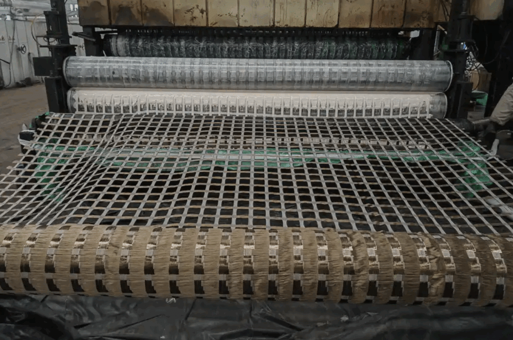
4. Applications of Geogrid Reinforcement
With outstanding performance in reinforcement, anti-cracking and slope stabilization, geogrid reinforcement has become a standardized civil engineering process. Its core application scenarios cover road engineering, retaining wall engineering, soft foundation treatment and slope protection, adapting to regular and complex geological conditions.
4.1 Reinforcement of Retaining Walls
In mechanically stabilized earth retaining wall construction, uniaxial geogrids are laid in layers inside wall backfill. Interlocking between geogrids and backfill counteracts lateral earth pressure and boosts overall wall stability, resolving drawbacks of traditional retaining walls such as excessive self-weight, high cost and susceptibility to deformation and cracking. This process delivers convenient construction and strong structural integrity, widely adopted in municipal retaining walls, highway slope retaining walls and residential area fill retaining walls.
4.2 Stabilization of Roads and Pavement Base Courses
In municipal highways, rural roads and factory access roads, biaxial geogrids are laid at the optimal reinforcement layer between subbase and base course. They effectively disperse dynamic vehicle loads, block upward propagation of reflective cracks from base layers, restrain differential subgrade settlement and improve pavement flatness and durability. Meanwhile, they optimize subgrade filler performance, reduce consumption of high-quality fillers and cut comprehensive road construction costs.
4.3 Reinforcement Treatment of Soft Soil Foundations
For soft soil, silt and collapsible loess distributed in coastal and riverside areas, geogrid reinforcement rapidly improves soil mechanical properties, raises overall foundation bearing capacity, restricts plastic deformation of soft soil and accelerates foundation consolidation settlement to avoid later settlement and collapse of projects. Compared with traditional replacement filling and pile foundation reinforcement, geogrid reinforcement shortens construction periods and lowers costs, ideal for large-area pre-treatment of soft ground.
4.4 Stabilization Protection of Embankments and Slopes
In highway embankments, water conservancy dykes and artificial fill slopes, geogrids are laid in layers within fill soil. They greatly enhance shear and anti-sliding capacity of fill soil to prevent slope collapse, soil sliding and loss. Combined with slope vegetation and protective nets, they integrate structural reinforcement and ecological protection, fitting complex working conditions of high fills, steep gradients and water-facing slopes.
5. Comparison Between Geogrid Reinforcement and Traditional Reinforcement Methods
Traditional soil reinforcement technologies such as steel bar reinforcement, soil cement solidification and soil replacement filling feature high costs, long construction periods, poor durability and limited adaptability to working conditions. As an innovative flexible reinforcement technology, geogrid reinforcement delivers remarkable comprehensive engineering advantages.
Compared with steel reinforcement, geogrids boast outstanding corrosion and anti-aging resistance. Buried in humid, acid or alkaline soil, they will not fail due to rust, completely eliminating structural damage caused by steel corrosion. Meanwhile, geogrids are lightweight for convenient transportation and laying without large mechanical equipment, cutting material and labor costs. Their flexible structure accommodates minor soil deformation and avoids structural fracture.
Compared with soil cement solidification and replacement filling, geogrid reinforcement eliminates massive soil excavation and replacement as well as long curing periods, greatly shortening construction schedules. It preserves the original soil ecological structure with low carbon emissions and no secondary pollution, meeting requirements of eco-friendly infrastructure projects. Additionally, geogrid reinforcement distributes stress more evenly to avoid common defects of traditional reinforcement including local stress concentration and incomplete stabilization.
Overall, geogrid reinforcement integrates economic efficiency, practicality, durability and environmental friendliness. Except for extreme ultra-high load and special geotechnical conditions, it can replace most traditional soil reinforcement methods and serves as the preferred solution for current geotechnical reinforcement projects.
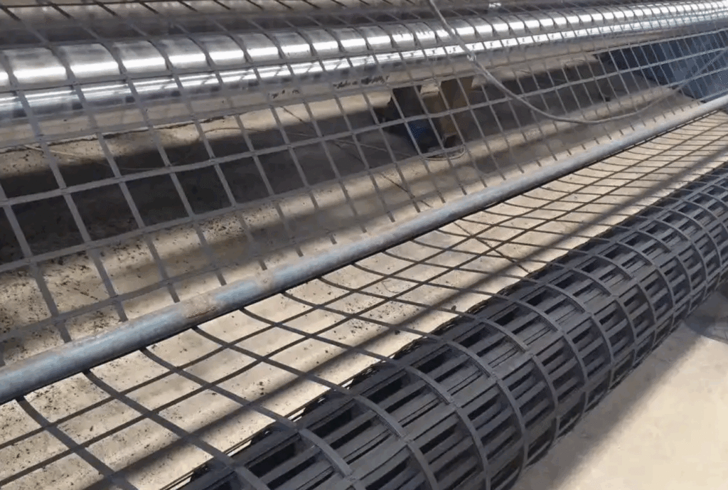
6. Construction Procedures of Geogrid Reinforcement
Standardized construction techniques are critical to guarantee reinforcement effects of geogrids. Strict compliance with national standard construction procedures avoids hidden risks including wrinkled laying, insufficient overlapping and insecure fixation, maximizing the material’s stabilizing performance.
6.1 Foundation Treatment Before Construction
Clear the laying surface thoroughly before construction, removing stones, sharp debris, weeds and silt to ensure a flat, compact and intact base without protrusions. The compaction degree of the foundation shall meet engineering design standards to prevent geogrids from being pierced by sharp objects and create basic conditions for sufficient interlocking between geogrids and soil.
6.2 Geogrid Laying, Tensioning and Fixation
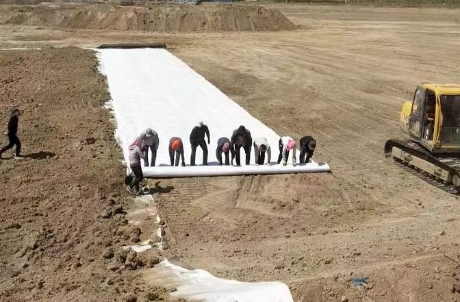
Lay geogrids according to engineering stress directions: the main force-bearing direction of uniaxial geogrids shall be perpendicular to soil sliding surfaces or embankment axes, while biaxial geogrids shall be laid flat without directional deviation. Keep geogrids smooth, taut and wrinkle-free during laying. Fix ends with U-shaped nails or steel spikes at intervals of 2 to 3 meters for general areas; narrow intervals down to within 1 meter for corners, joints and slope edges to prevent geogrid sliding and loosening.
6.3 Overlap Treatment, Layered Backfilling and Compaction
Follow national standard specifications for geogrid overlap width: a minimum overlap of 15 cm for conventional civil engineering projects, and no less than 20 cm for heavy-load subgrades, high fills and water-facing slopes. Fasten overlaps via binding or mechanical stitching to guarantee integral connection.
After inspection and acceptance of laid geogrids, backfill soil in layers with the first filling layer controlled at 20–30 cm thickness. Filler particle sizes shall conform to design requirements. Compact soil evenly in layers and prohibit heavy machinery from directly rolling geogrids to prevent damage.
6.4 Key Construction Prohibitions and Common Mistakes to Avoid
It is forbidden to lay wrinkled or suspended geogrids with insufficient overlap width, backfill oversized particles or compact excessively thick soil layers at one time. Do not leave geogrids exposed under direct sunlight for long after laying; backfill covering soil promptly to avoid accelerated material aging by ultraviolet radiation and weakened long-term mechanical performance.
7. Engineering Advantages and Limitations of Geogrid Reinforcement
7.1 Core Engineering Advantages
In terms of engineering performance, geogrid reinforcement significantly improves soil shear, compressive and anti-sliding capacity, effectively controlling foundation settlement, pavement cracking and slope instability, and extending the overall stability and service life of civil structures.
Economically, geogrids feature low material costs and convenient construction without prolonged curing, shortening construction periods, reducing labor and equipment expenses and requiring almost no maintenance in later operation.
Environmentally, geogrids are recyclable, low-carbon and pollution-free without damaging original soil structures, complying with eco-engineering construction standards. They adapt to various complex geological conditions including soft soil, steep slopes and water-facing areas with strong universality.
7.2 Applicable Limitations and Optimization Solutions
Geogrid reinforcement is not suitable for projects with ultra-heavy loads, extreme frozen soil or special chemical sites with strong corrosion, where single geogrid reinforcement delivers limited effects. Meanwhile, low-quality geogrids are prone to tensile fracture and aging failure, and non-standard construction drastically weakens reinforcement performance.
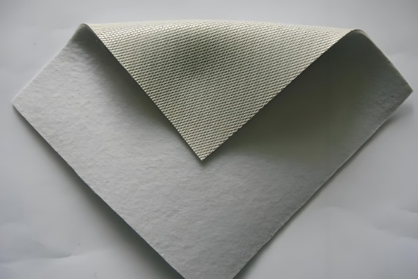
In practical engineering, select high-strength geogrids meeting national standards, optimize layered construction processes, or combine geogrids with drainage boards and geotextiles to make up for adaptability defects under special working conditions and guarantee reinforcement quality.
Frequently Asked Questions
1、Which type of geogrid is better for road construction?
Biaxial geogrids are prioritized for conventional municipal roads, rural roads and floor subgrades to meet demands of full-plane load bearing, anti-cracking and settlement control. Uniaxial geogrids can be matched for road slope and embankment side reinforcement to resist lateral soil sliding, achieving better effects through combined application.
2、What is the service life of geogrid reinforcement?
HDPE and PET geogrids that comply with national standards can serve over 50 years under normal working conditions when buried in soil away from ultraviolet radiation and acid-base erosion, fully meeting service life requirements of permanent projects such as highways, municipal works and water conservancy facilities.
3、Is geogrid laying necessary for courtyard driveways and small floor slabs?
Yes. The soil bearing capacity of subgrades under small driveways and concrete floors is weak, prone to settlement and cracking under long-term vehicle rolling. Laying biaxial geogrids effectively reinforces base courses and disperses loads to avoid later pavement damage and extend floor service life greatly.
Conclusion
Supported by mature mechanical principles, outstanding reinforcement effects and economical construction costs, geogrid reinforcement has become a core technology in modern geotechnical stabilization engineering. The core logic for material selection is as follows: adopt uniaxial geogrids for laterally stressed scenarios such as slopes and retaining walls, and biaxial geogrids for plane load-bearing scenarios including subgrades, soft foundations and floor slabs.
In practical engineering application, select geogrids with corresponding materials and tensile strength according to site geological conditions, structural stress forms and engineering load grades. Meanwhile, strictly follow standardized construction procedures and control key links including foundation treatment, laying & tensioning, overlapping and compaction to maximize reinforcement effects, evade engineering quality hazards and strike an optimal balance among engineering safety, quality and costs. With the lightweight and eco-friendly development of infrastructure projects, geogrid reinforcement will see expanding application scenarios and remain a mainstream solution for geotechnical stabilization works.
References
[1] GB/T 17689-2008 Geosynthetics – Plastic geogrids
[2] Theory and Engineering Application of Geogrid Reinforced Soil Structures (Authoritative monograph on geotechnical engineering)
[3] Construction Technical Specifications and Engineering Effect Evaluation Standards for Soft Soil Foundation Reinforcement of Expressways